Front A-Arms
Home Up Products Projects Events Photo Album Other Fabrication Our Shop Tools Our Other Toys Product Reviews For Sale Links Guest Book Contact Us

Home
Up


The time has finally come to step up to the next level in suspensions.  I have decided to create a new tube chassis Baja with airbags and A-Arm front suspension.  I will be using a Ford Mustang power rack and pinion steering, custom spindles and arms with full hiem joint adjustment.  -MJ


rearurethanebushings.jpg (76460 bytes)
I was going to build it for Urethane bushings because of the cost of hiem joints but found a set of 20 on Ebay for $32 including shipping.  I couldn't pass that up. 


frontheims.jpg (53269 bytes)
Above shows the hiem joints and the tube adapters I made for the a-arms.  The tube adapters are thick walled and drilled and tapped for the inboard 5/8" rod ends and will weld into the a-arm tubes.  The larger one is for the 7/8" rod ends that will make up the outboard mounts.


jigtable.jpg (68756 bytes)
The first thing I needed to do was build a jig table so I could weld all this together and have them straight and the same.  I just used some 1.5" square tube and a 3' square sheet of 1/4" plate with some casters on the bottom and I had a table.


tapadapter.jpg (47383 bytes)  a-armtubeadapterlathe.jpg (75188 bytes)
I also had to make an adapter to fit the 7/8" tap into the tail stock of my lathe so I could tap the big adapters.  My tail chuck was not big enough to fit that monster tap into.


Now the real work begins.  The plan is to have a center frame section of 20" to accommodate the Ford rack, and have 18" long arms for what should be 20" of front travel.

a-arm15.jpg (63024 bytes)  a-arm16.jpg (72558 bytes)    

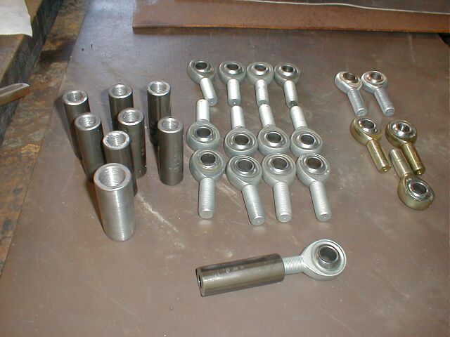
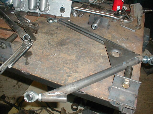
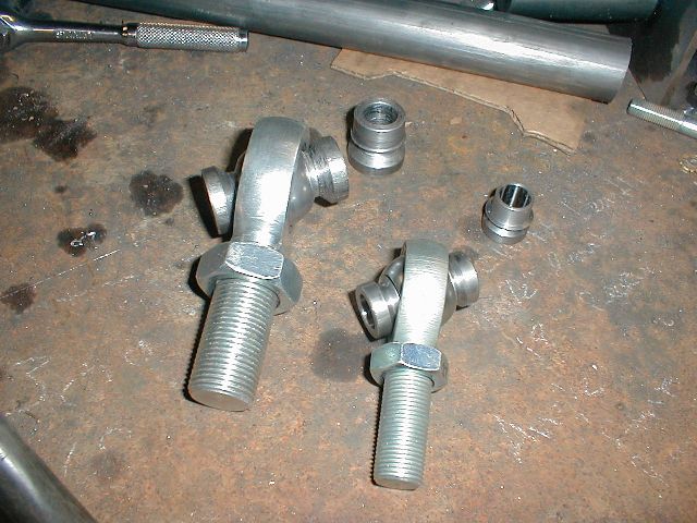
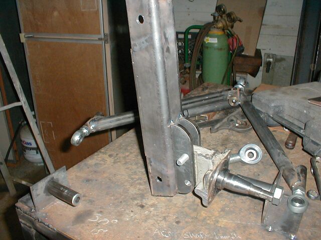
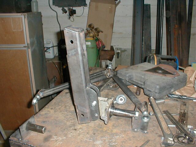
A simple jig was made to hold the tube adapters in place.  1.25 diameter tubing was then cut to length and notched to merge into the rod end holders.  A triangle of 11ga was added to the end joint for rigidity and my amazing but useless sheet metal dimpler was used to make a fancy hole.

a-arm18.jpg (63934 bytes)  a-arm19.jpg (64148 bytes)  a-arm20.jpg (54245 bytes)  a-arm22.jpg (62061 bytes)  a-arm23.jpg (66457 bytes)  

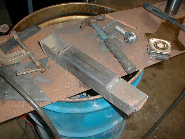
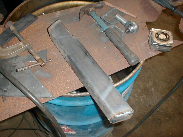
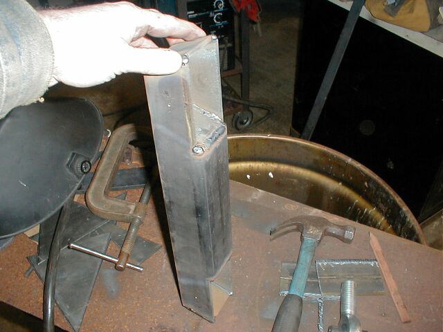
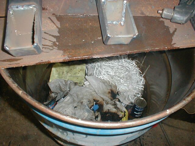
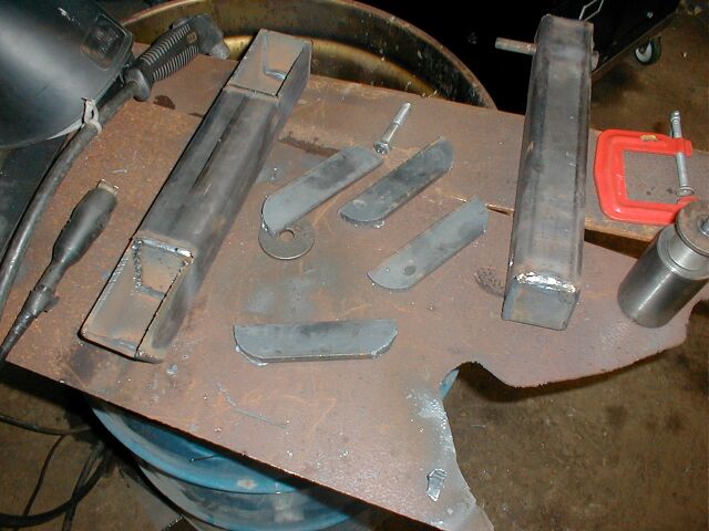
The spindle was made of heavy wall square tubing with a section of the side cut out on either end.  Flat bar was then used to fill in the gaps and frame the opening for added strength and to maintain the rigidity of the spindle.  One thing to keep in mind is whether or not someone put flammable garbage into your makeshift welding stand.  You will find out right away as soon as the flames are big enough to flicker around the sheet metal on top of the barrel.  Oh what fun!

a-arm17.jpg (56911 bytes)  a-armheimspacers.JPG (75458 bytes)  a-arm26.jpg (60527 bytes)  a-arm36.jpg (52426 bytes)  a-arm34.jpg (53312 bytes) 

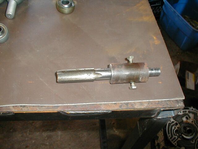
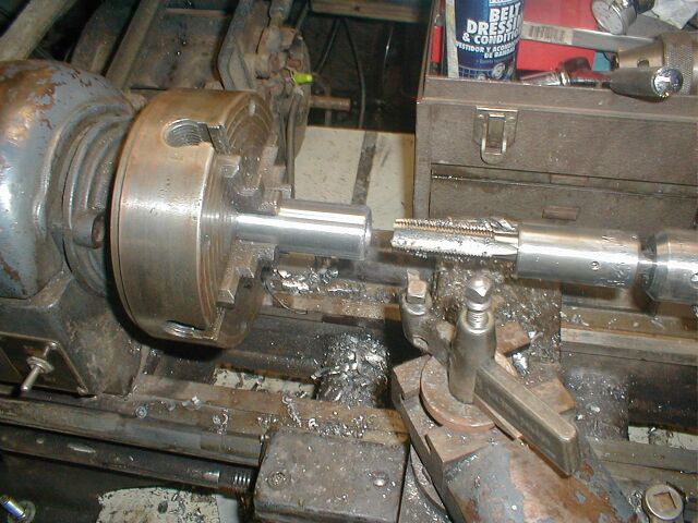
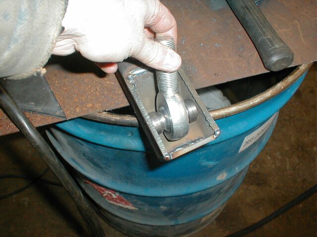
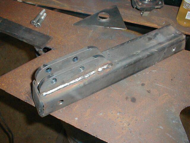
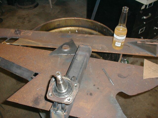
Holes were drilled in the tubing for mounting the rod ends with misalignment spacers.  3/8" flat bar was then drilled and shaped to mount the spindle to.  I found that a '75 or later super beetle spindle has a bolt on flange on the end of it with the right angle.  I opted for that instead of a full custom for ease of replacement.  Time will tell on how strong they are.

a-arm31.jpg (64365 bytes)  a-arm32.jpg (64005 bytes)


For problems or questions regarding this web contact .
Last updated: February 27, 2014.

All content on this website belongs Blind Chicken Racing and it's employees.  All use without prior permission is expressly forbidden.  Violators will be prosecuted.