If
you have any questions regarding this Project please E-mail
"INSAYN".
There are No Plans for this bender, none
now, and none later.
I want you to think freely and create.
After
receiving enquiries weekly on how is this was thing built, I decided to at least
add all
the pics I have of the bender. I was not expecting the amount of
interest that the bender has generated, therefore no plans were drawn up
Keep in mind that I built it from scratch
for a purpose, and if you decide to build your own, feel free to, as well as
make as many changes as you need. NOTE: If I were to build another of this
style, I would make the bottle jack mount on top, out of tube horizontally, with
a 1" solid bar running through the sides of the frame, and through the
tube. It would be made with the same 1" bar and 1.5"x .25"
wall DOM tube parts as the die pivot.
If you are successful and happy with your
results, please send me some pics of your bender, so I can add them here for
everyone to see the variations that you came up with. This site is all
about sharing.
------------------------------------------------------------------------------------------------------------------
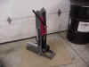
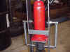
You just can't go building a tube chassis without a tube bender, right?
I was reluctant to spend big bucks on a commercial built bender,
so I built my own.
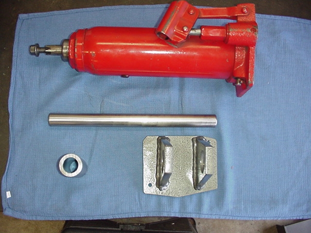
I called up Pro-Tools in Florida, and
chatted with one of the guys that works there about my options. He was very
interested in making sure I bought only what I needed, and nothing more. The guy
was great! He talked me through all the available parts that go into a tube
bender. I gave him my general idea over the phone, and he was able to set me up
with what I needed, take the order, and have it ready to ship the next day. The
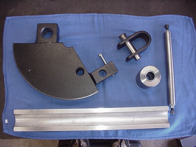
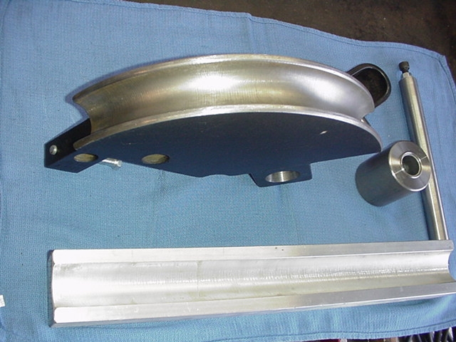
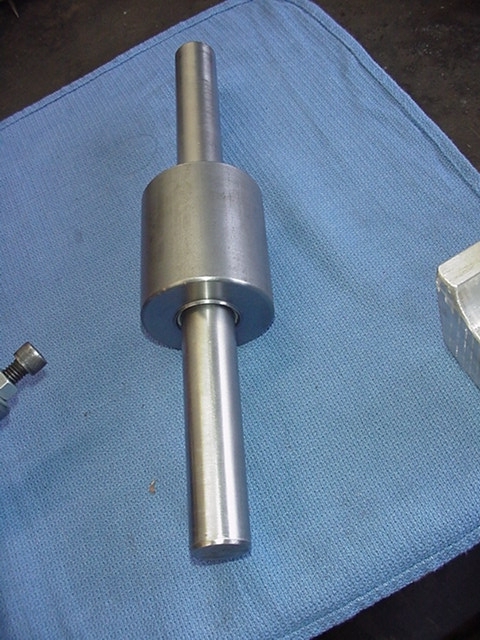
120 degree, 1.5" diameter X 7" radius die set, plus roller w/Teflon impregnated bushings, and a 1" diameter pivot shaft was at my door less
than two weeks.
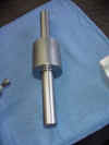
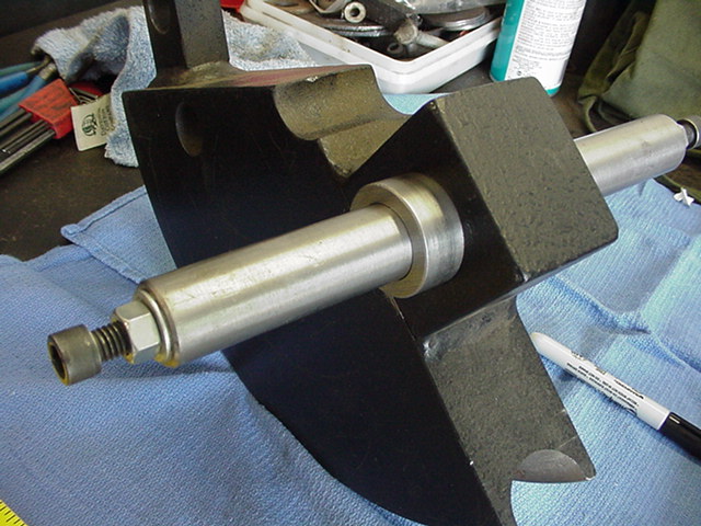
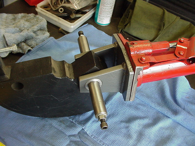
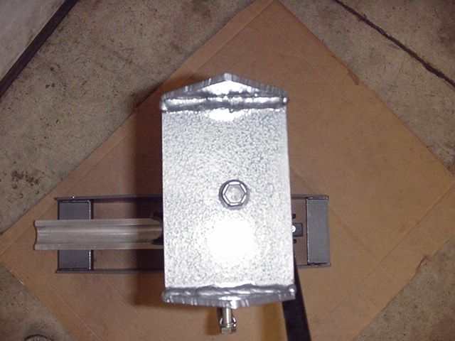
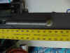
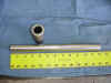
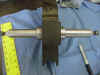
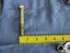
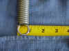
The solid rod here is something a material that I cannot remember the name
of, but is kinda like tool steel. It has exact tolerance of 1", and
is less prone to bending than mild steel rod. So far it has no signs of
bending, and I have bent .120" wall tubing with ease.
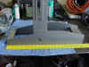
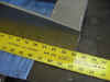

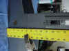
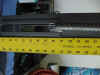
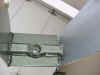

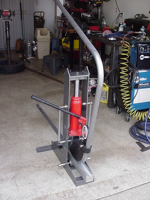
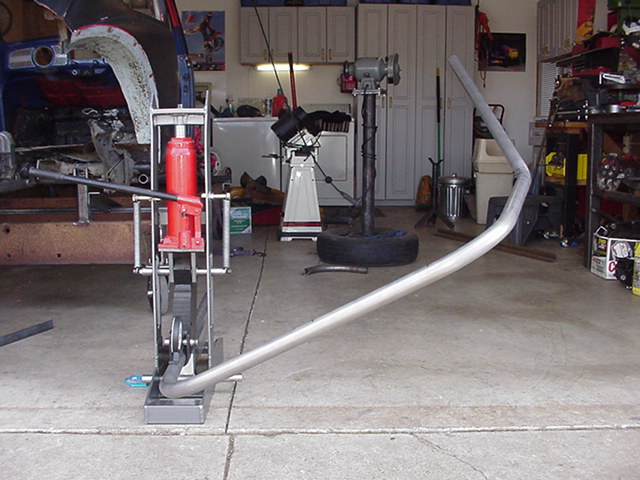
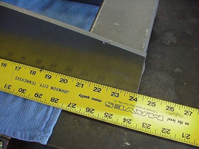
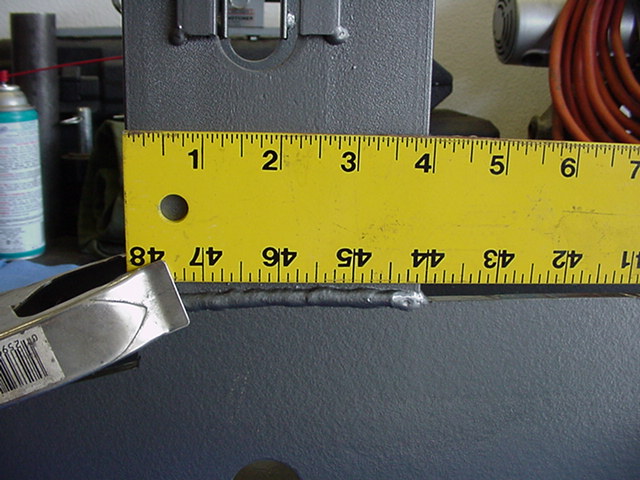
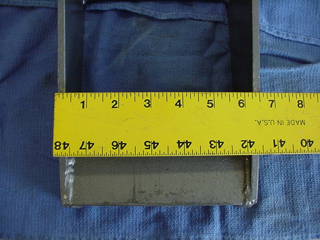
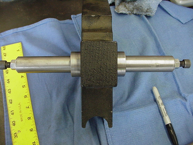
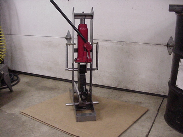
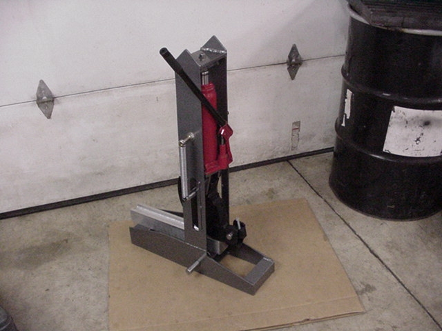
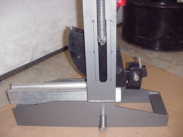
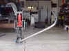
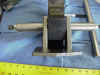
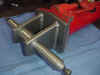
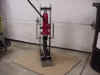
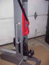
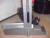
Here is the framework, and some dimensions added. You can see that
there is a yellow yard stick placed along the various parts making it easy to
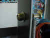
get the length and width of parts. All holes for the rods were drilled
with a 1" holes saw. The slot opening for the pivot rod was made by
drilling two 1" holes, and then connecting them with the plasma
cutter. I made a 1/8" offset on ether side of the opening to fit in a
piece of angle iron (1/2" x 1/8") . This give the horizontal rod
a flat guide, so as not to gouge it as it is put through its travel up and
down.
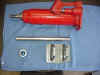

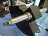

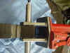
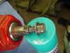
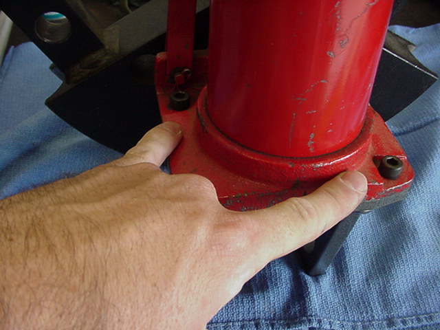
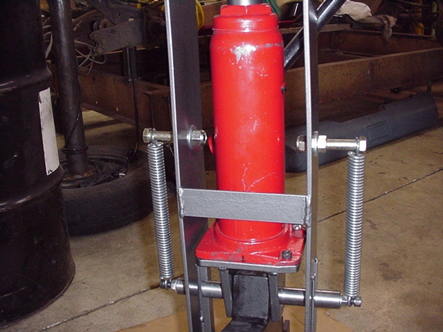
The hydraulic jack is a 12 ton unit with about a 6" throw. Anything over
10 ton should be enough for roll cages.
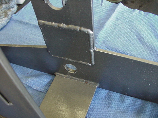
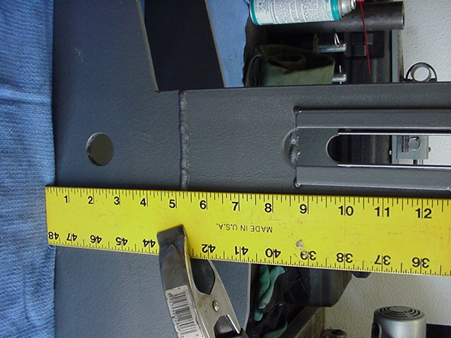
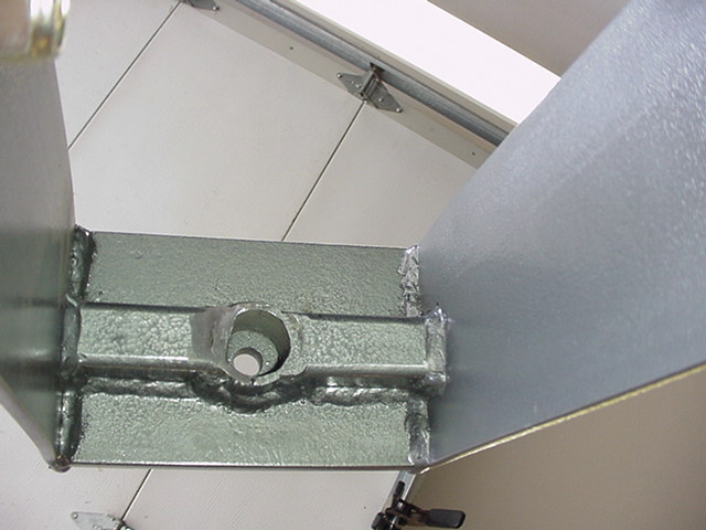
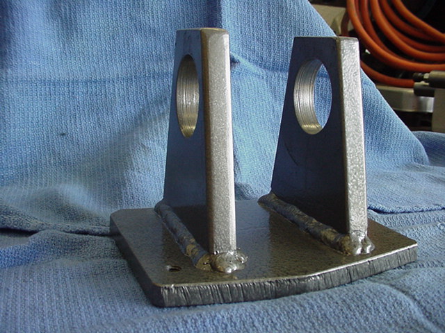
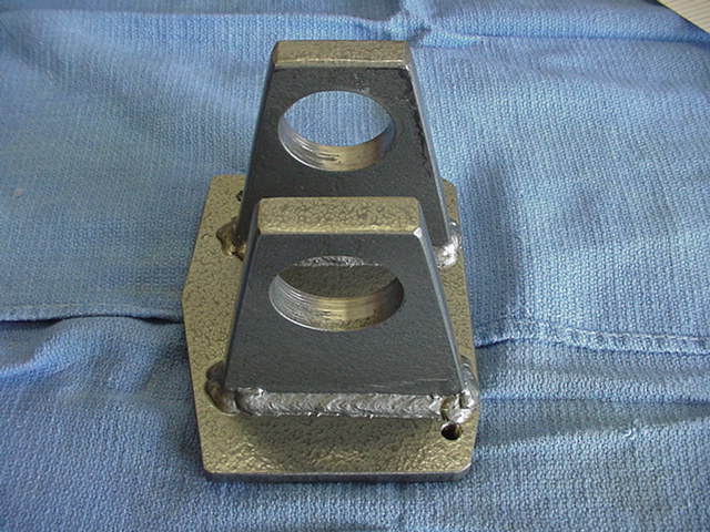
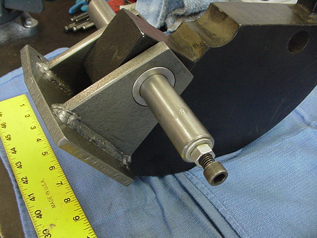
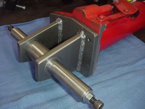
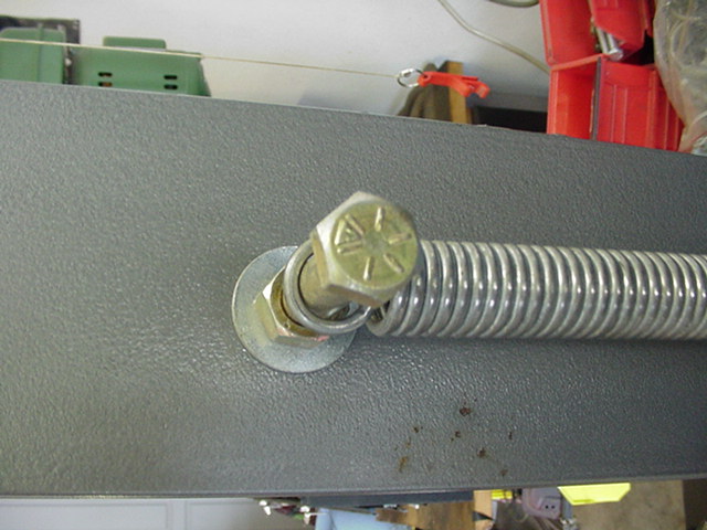
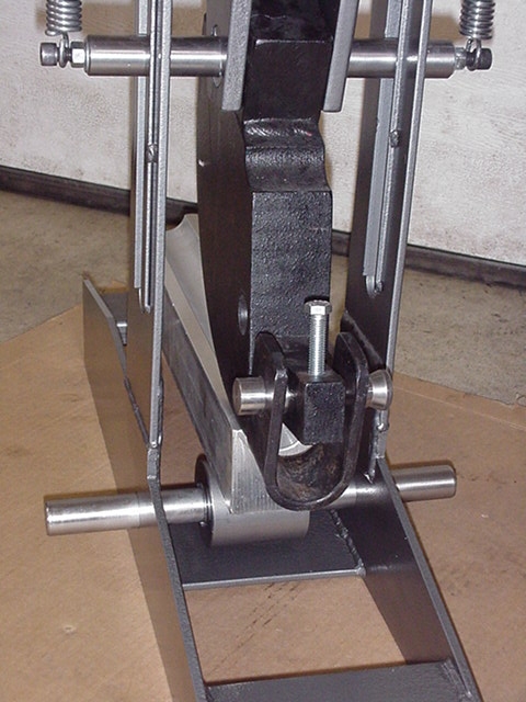
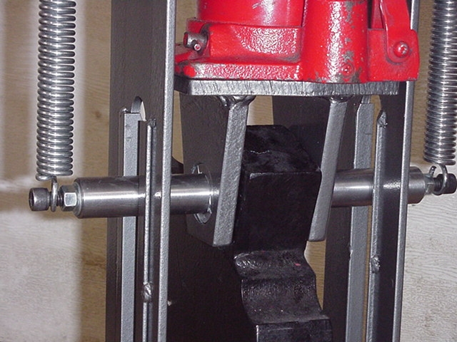
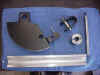
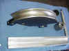
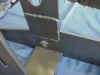
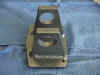
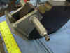
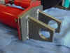
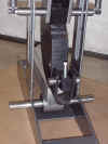
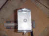
The piece bolted to the bottom of the hydraulic jack is the pivot point for
the die. It is made up of 3/8" and 1/2" plate mild steel, drilled 1.5" for
the pivot bearing (1.5"Dia X .25" wall - DOM tubing). The shaft with
the bolts hold the pivot straight in the bender frame, as well as the attachment
for the return springs.
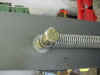
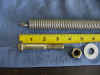
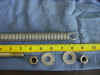
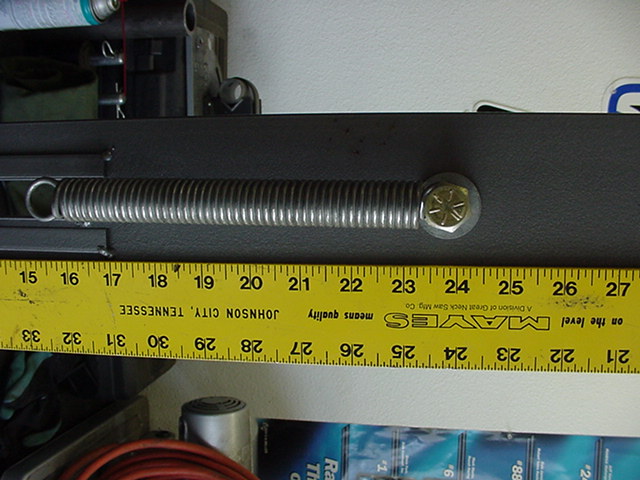
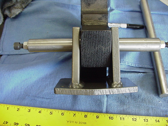
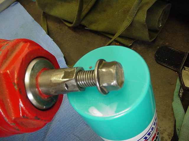
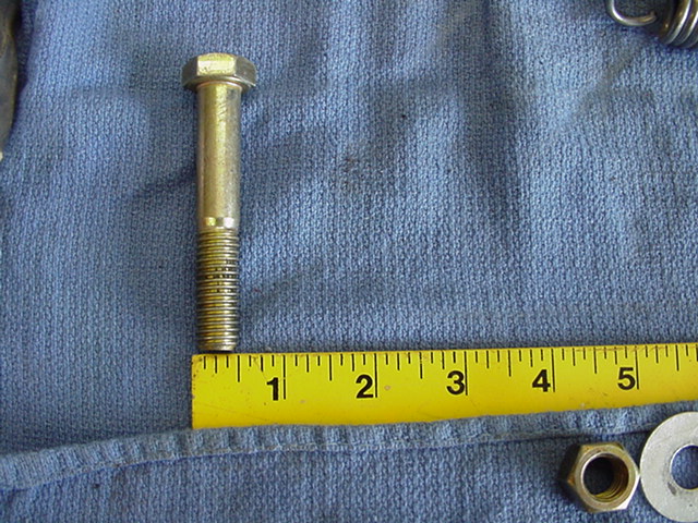
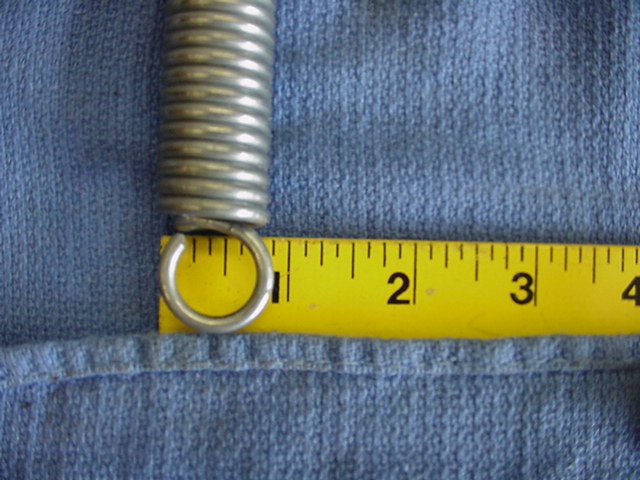
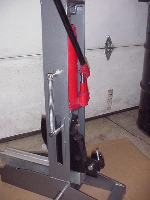
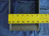
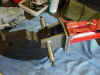
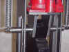
Here is the hardware for the spring mounts. Simple Grade 8 bolts/nuts,
and a set of springs from ACE hardware. I think the springs are rated for
6" of stretch, and 100 lbs each for return pull. They turned out to
be perfect for this project.
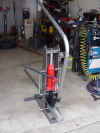
I got busy and built the whole thing with very simple plans, (chalk drawings
on the floor). It worked, it bends, I'm very happy, and not $$$ broke from just
buying one. I think I have right around $300-$325 into it complete, and it is capable of utilizing more of the Pro-tools dies.
Remember, if you use my bender as a reference, all
I ask of you is to send me some pics of
yours to add here. I would like to see how the idea evolves, and share
your work with everyone else.
If you want to see it used in action, click
here.